
NEMA Wiring Schematic Manual for Electrical Experts
Approximately 70% of electrical breakdowns within establishments result from substandard wiring methods. This fact underlines the necessity of following established protocols, highlighting NEMA wiring diagrams’ significance for electrical specialists. Via these schematics, wiring setups that fulfill both functional efficiency and optimal security norms are outlined.
The objective of this manual is to equip electrical experts with comprehensive understanding into NEMA norms. Stressing the value of accurate electrical setups is crucial. Through mastering these principles, specialists can drastically reduce the likelihood of accidents and confirm they meet safety standards endorsed by Installation Parts Supply. Knowledge in l14-30 plug wiring diagram is vital whether designing new systems or servicing current ones, as it boosts the ability to provide secure and consistent electrical systems.
Primary Highlights
- NEMA wiring schematics are essential for maintaining electrical safety and compliance.
- Correct wiring techniques can minimize electrical issues significantly.
- Grasping NEMA standards enhances the effectiveness of electrical arrangements.
- Installation Parts Supply encourages compliance with safety protocols in electrical operations.
- NEMA diagrams cover a wide range of functions across various fields.
Comprehending NEMA Criteria and Their Importance
NEMA criteria are pivotal in the electrical field, guiding safety and operation precisely. Developed by the National Electrical Manufacturers Association, they set pivotal standards for designing, examining, and marking electrical gear. Such measures guarantee uniformity and dependability across all electrical installations, which is of great value.
Identify the NEMA Criteria?
NEMA designations vary from classes 1 up to 13. Every level defines the conditions suitable for electrical devices to function optimally. For instance, NEMA 1 delivers minimal indoor security but lacks dust protection. On the other hand, NEMA 4 ensures appliances is waterproof, a must for surviving significant water immersion. Understanding these designations is key in selecting suitable devices.
Why NEMA Criteria Matter for Electrical Safety
The role of NEMA criteria in maintaining electrical security is substantial. They are instrumental in minimizing shock risks, apparatus failures, and burn risks. Proper adherence to NEMA standards allows equipment to perform safely under specific environmental conditions. For open-air deployment, NEMA 3 classifications provide protection against the environment, guarding the device from harsh weather like downpour and snowfall. In regions at risk of explosions, classifications such as NEMA 7, 8, and 9 are critical for maintaining safety.
Applications of NEMA Standards in Wiring Schematics
The use of NEMA criteria in wiring diagrams is vital for safe, optimal electrical setups. These diagrams utilize consistent symbols and layouts originating from NEMA standards, streamlining the understanding of complex electrical arrangements. Such standardization is helpful. It fosters transparency, consistency, and diminishes errors, thereby enhancing electrical protection across residential and industrial sectors.
NEMA Wiring Diagram Essentials
NEMA wiring schematics are crucial for electrical experts, making complicated linkages transparent. They outline the linkages and components in diverse installations. By understanding the components, kinds, and symbols of NEMA schematics, professionals can improve their performance in installations and maintenance.
Constituents of NEMA Wiring Diagrams
NEMA schematics include crucial parts for specific electrical setups. You’ll see wiring terminals, connectors, and various equipment for secure junctions. Each piece guarantees energy is distributed optimally, complying with security standards.
Categories of NEMA Wiring Drawings
NEMA uses different schematics, like linkage blueprints and electrical layouts. These schematics depict device relationships, while designs show power flow. Choosing the appropriate diagram helps with diagnostics and setup.
Typical Symbols Employed in NEMA Wiring Diagrams
Symbols in wiring drawings are essential for effective clarity. They illustrate switches, networks, and interfaces. Recognizing these symbols aids teams interpret schematics properly. This ensures installations adhere to NEMA norms.
NEMA Wiring Schematic Characteristics
For electrical specialists, understanding the key elements of accurate electrical wiring schematics is crucial. These drawings provide both lucidity and thoroughness, synchronizing setups with NEMA norms. They demand exact annotation and scaling to minimize setup mistakes. This fosters a protected and highly efficient workplace.
Essential Characteristics of Accurate Electrical Wiring Diagrams
Correct electrical wiring diagrams are indispensable in electrical undertakings. They encompass important qualities such as:
- Clarity: Schematics must be unambiguous, minimizing misinterpretation risks.
- Wholeness: They need to contain all essential parts, connections, and electrical classifications.
- Adherence to Standards: Complying with NEMA standards is non-negotiable for guaranteeing security and operation.
- Detailed Labeling: Clear labels on each element are crucial for grasping and avoiding mistakes.
- Proper Sizing: The scales should replicate the real setup to portray the configuration correctly.
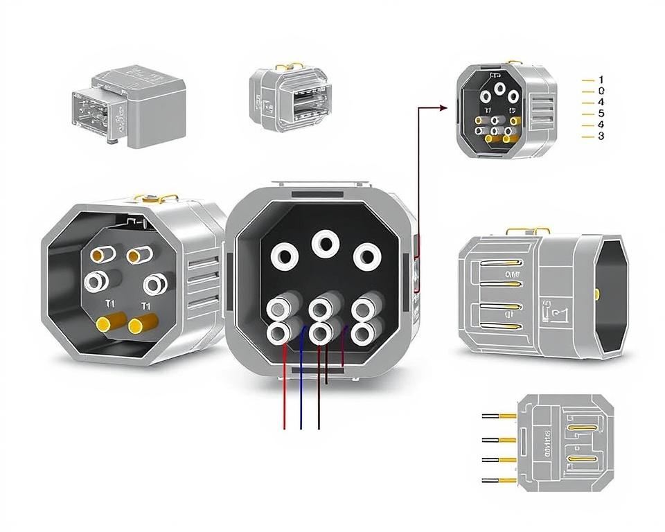
Comprehending NEMA Coupler Configuration
The insight into NEMA coupler configuration is vital for making accurate junctions in electrical setups. Understanding of distinct pin configurations ensures protection and appliance performance. There are a range of NEMA connectors, intended for specific power levels and currents, covering:
| NEMA Connector Type | Amperage Rating | Voltage Level |
|---|---|---|
| L5-15 | 15A | 125V |
| L5-20 | 20A | 125V |
| L14-20 | 20A | 125/250V |
| L1430C | 30A | 125/250V |
| L620C | 20A | 250V |
| L1430C | 30A | 125/250V |
| L630R | 30A | 250V |
Understanding NEMA connector pinouts is vital for stable linkages, boosting performance. It’s paramount to match couplers with equipment properly using twist-lock or linear blade types, to prevent dangers.
NEMA Appliance Wiring
NEMA device wiring encompasses multiple arrangements for safe electrical device connections. These standards confirm that equipment integrate securely, lowering danger. Understanding the different NEMA devices and their wiring is crucial for electricians.
Different Categories of NEMA Devices
NEMA categorizes devices by kind based on power levels and amperage requirements. Essential configurations are:
- 2-Pole 2-Wire
- 2-Pole, 3-Wire with Grounding
- 3-Pole 3-Wire
- 3-Pole 4-Wire Grounding
- 4-Pole 4-Wire
- 4-Pole, 5-Wire with Grounding
These arrangements find use in homes and manufacturing plants, supporting 125V, 208V, and 480V.
NEMA Outlet Wiring Explained
NEMA plug wiring differs to suit multiple energy requirements, with rotary-lock types delivering consistent junctions in shaky settings. For instance, the L5-15 plug operates at 15 amps, frequently used in enterprise settings, whereas the L14-20 is intended for 20 A at 125/250 V.
The NEMA naming scheme helps in selecting the correct plugs, spotlighting attributes like electrical polarity and grounding. Such accuracy guarantees that appliances operate securely.
NEMA Receptacle Wiring Instructions
Accurate wiring of NEMA sockets aligns with electrical codes and safety guidelines. Such as, L530R receptacles should be wired for 30 amperes at 125 V, with L630R options for 250 volts. Correct grounding is crucial to dodge electrical accidents.
Opting for certified NEMA plugs and receptacles ensures safe, code-compliant installations. It’s imperative to consult formal protocols when installing.
NEMA Motor Wiring and Uses
NEMA motor wiring is vital in electrical design, especially for industrial use. Knowing how NEMA motor configuration works ensures that motors are installed for optimal performance. Motors, like one-phase and tri-phase types, demand proper wiring to work safely and effectively.
Overview of NEMA Motor Wiring
Understanding NEMA motor wiring necessitates knowledge of junctions and arrangements. Most three-phase motors now support dual-voltage, signifying they can work on both low (208-230V) and high voltage levels (460V). Wiring at high voltage results in lower current draw than at low voltage. High voltage perks include smaller wires for the input, a notable benefit for units exceeding 10 HP.
While both NEMA and IEC units are utilized in the market, NEMA variants are generally bigger and more costly than IEC ones for under 100 HP deployments. NEMA controllers range from size 00 to 9, suitable for diverse functions. A common characteristic in NEMA controllers is a Trip Class of 20, intended to trigger when a motor’s amperage exceeds six times the rated current in 10 s.
Selecting the Appropriate NEMA Motor Setup
Choosing the right NEMA motor configuration affects overall performance and safety. A standard three-wire control circuit utilizes three wires for a start/stop pushbutton panel, allowing simple motor operation. Frequent three-phase configurations include the 12 Lead Dual Voltage and 6 Lead, facilitating Wye and Delta configurations.
IEC motor starters often include phase monitoring, increasing safety. They also feature adjustable Trip Classes for tailored protection in low voltage operations. Additionally, many units have thermal protection, critical for Single Phase and Dual Voltage configurations.
| Configuration Type | Voltage Level | Current Specification | Common Application |
|---|---|---|---|
| 12 Lead Dual Voltage | Dual Voltage (208-230V / 460V) | Dependent on motor size | Wye Start and Delta Run setups |
| 6 Lead | Single or Dual Voltage | Up to 32 amps | Wye or Delta connections |
| Single Phase | One Voltage | Ranges from 1 to 5 amps | Dual Speed and Dual Winding setups |
| Delta Connection | High Voltage | Variable | Various applications including Current Transformers |
Final Thoughts
Comprehending NEMA wiring diagrams and norms is essential for electrical professionals seeking to improve their expertise and follow electrical safety standards. These guidelines secure safe and efficient electrical setups but also avoid hazards associated with incorrect wiring. As discussed, following NEMA standards yields the augmented performance of various NEMA appliances and systems.
For technicians, the choice of quality resources can profoundly influence the success of their tasks. Installation Parts Supply provides a vast selection of wiring items aligned with NEMA norms. This empowers professionals to access critical elements for fulfilling these important requirements. High-quality resources and comprehensive expertise of NEMA wiring schematics greatly enhance system security and efficiency.
During electrical deployments, always place protection and precision first. Mastering NEMA standards delivers the insight necessary for executing industry standards accurately. This secures that each electrical junction established conforms to superior norms.
FAQ
Which are NEMA wiring schematics?
NEMA wiring schematics display the configurations and connections of NEMA-standard electrical gadgets. They adhere to safety and operational norms defined by the National Electrical Manufacturers Association.
What makes NEMA standards vital for electrical protection?
NEMA norms are fundamental to defining safety and performance benchmarks for electrical gear. These standards help electrical experts lower electrocution risks, device malfunctions, and fire hazards.
Identify the key parts are essential in a NEMA wiring drawing?
Essential components in a NEMA wiring schematic consist of circuit setups and linkage diagrams. These diagrams also include detailed markings and depict the electrical system’s different parts correctly for deployments.
Which kinds of NEMA wiring drawings are available?
Diverse NEMA wiring drawings address various applications, including energy distribution layouts and connector schematics. Each design plays a unique role in electrical systems.
Which are the typical symbols used in NEMA wiring schematics?
Common symbols in these schematics depict switches, circuit breakers, outlets, and other elements. Utilization of these symbols encourages unambiguous interaction and correct interpretation of wiring schematics.
Identify the essential attributes of precise electrical wiring diagrams?
Accuracy in electrical wiring schematics is defined by their clarity, thoroughness, and explicit annotation. They must align with NEMA criteria to avert faults in installation.
Define a NEMA connector layout?
A NEMA connector configuration outlines electrical connections at a connector, displaying distinct pin functions. This secures reliable and optimal junctions in electrical systems.
Which are the various kinds of NEMA appliances?
NEMA units include various electrical outlets and interfaces, like plugs and receptacles. They are crafted for different ampere and voltage requirements to meet unique usage needs.
In what way is NEMA plug wiring configured?
NEMA plug wiring is determined by defined ampere and voltage needs, complying with security protocols and regulatory standards for multiple electrical uses.
What guidelines are there for NEMA outlet wiring?
Standards for wiring NEMA receptacles stress following electrical standards, guaranteeing correct polarity, and selecting proper gauge sizes. This maintains both security and functionality in electrical setups.
Describe how to wire a NEMA motor effectively?
To set up a NEMA motor, one must comprehend its defined single-phase or three-phase configuration. Selecting the appropriate wiring approach is vital, along with maintaining electrical safety for enhanced motor performance.
Which factors should be considered when choosing a NEMA motor configuration?
Selecting a NEMA motor configuration necessitates an evaluation of the project’s voltage and current demands and performance traits. It’s also vital to confirm suitability with existing equipment for reliable operation and safety.